Carbon anode blocks are the unsung workhorses of industrial electrolysis—from aluminum smelting to chlor-alkali production. Yet operators often witness a frustrating phenomenon: premature disintegration, leaving behind piles of carbon debris and crippled productivity. The culprit? Oxygen’s relentless assault on anode materials. Understanding this degradation mechanism isn’t academic—it's key to extending anode life, cutting costs, and avoiding unplanned downtime.
When current flows in an electrolytic cell, oxygen generated at the anode surface doesn’t just bubble away harmlessly. It initiates two destructive pathways:
Direct Carbon Oxidation
Oxygen reacts with carbon atoms, producing gaseous oxides:
C + ½O₂ → CO
C + O₂ → CO₂
This consumes the anode structure, thinning it over time.
Binder Degradation (The Hidden Failure Mode)
Most industrial carbon anodes aren’t pure graphite—they’re composites bound with coal-tar pitch or resins. Oxygen radicals aggressively attack these organic binders, breaking their chemical bonds. As binders erode, carbon particles detach, causing catastrophic spalling (surface flaking). This explains the "pile of carbon debris" observed under failing anodes.
Micrograph Insight: Cross-sections of degraded anodes reveal binderless voids (dark areas) where oxygen penetrated grain boundaries.
Problem: Oxygen from oxide ions (O²⁻) attacks anode blocks at 960°C. Binder degradation causes "dusting" – fine carbon particles contaminating molten aluminum.
Cost: A single failed anode can disrupt cell stability, increasing power consumption by 5–10%.
Problem: Oxygen evolution side-reactions at brine electrolysis anodes accelerate binder oxidation. Pitting occurs, exposing fresh carbon to attack.
Consequence: Anode replacements every 3–6 months vs. 2+ years for optimized blocks.
Ultra-Low Ash Graphite (<0.1% ash): Reduces catalytic sites where oxidation initiates.
Dense Impregnation: Filling pores with carbonizable resins blocks oxygen diffusion paths.
Modified Pitch Binders: Adding antioxidant additives (e.g., boron compounds) slows binder oxidation by 40%.
Synthetic Resin Binders: Epoxy or phenolic resins offer superior oxygen resistance in acidic/alkaline media.
Ceramic Barriers: Thin Al₂O₃ or SiC layers applied via CVD shield the anode surface from reactive oxygen species.
Electroactive Coatings: Iridium oxide (IrO₂) on carbon anodes suppresses oxygen formation in water electrolysis.
Industry standards like ASTM D7542 simulate anode degradation:
Weight Loss Test: Samples exposed to air at 525°C; mass loss <5 mg/cm²/hr indicates robust performance.
CO/CO₂ Emission Monitoring: Measures gas evolution rates during electrolysis trials.
Performance Comparison:
Anode Type Binder System Weight Loss (mg/cm²/hr) Standard Pitch-Bound Coal-tar pitch 9.2 Antioxidant-Modified Boron-treated pitch 5.1 Resin-Bonded Phenolic resin 3.8
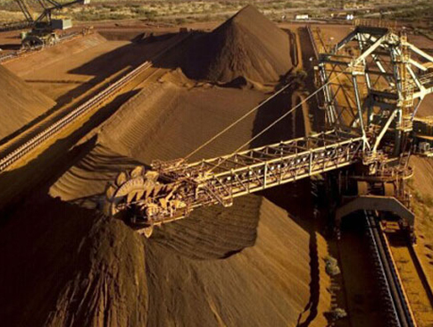
When a major Australian aluminum smelter switched to resin-bonded anodes with ceramic coatings:
Anode life increased from 28 to 42 days
Carbon dust contamination fell by 68%
Power savings: $1.2M/year
Not All Carbon Is Equal: Prioritize low-ash graphite with dense microstructure.
Protect the Binder: Antioxidant additives or synthetic resins combat the "silent killer."
Monitor Early Degradation: Track CO/CO₂ off-gases as a failure warning sign.
Layer Defenses: Combine material upgrades with protective coatings.
Oxygen attack isn’t inevitable—it’s a manageable challenge. By targeting binder integrity and surface reactivity, engineers can turn vulnerable carbon anodes into durable assets that withstand electrolysis’s harshest conditions.
 Industrial Co., Ltd.")
 English
 中文
中文 français
 Español
 русский
 português
 العربية
 tiếng việt
 Türkçe
 ไทย
ไทย فارسی
فارسی română